
Below are my initial notes from disassembling the Cambium 2400 Subscriber Module.
Powering up the subscriber module requires a 24v 400mA power supply; like the Ubiquiti power bricks. To make a power cord to power using the Ubiquiti brick requires a cord with a normal Ethernet termination on one end and reverse Blues and Browns on the other:
(White Orange, Orange, White Green, Blue, White Blue, Green, White Tan, Tan)
(White Orange, Orange, White Green, Tan, White Tan, Green, White Blue, Blue)
Ip is 169.254.1.1, shove a usb B end into the auxilary port on the bottom of the unit *(Not the Ethernet end).
http://www.ftdichip.com/Drivers/VCP.htm – get Driver
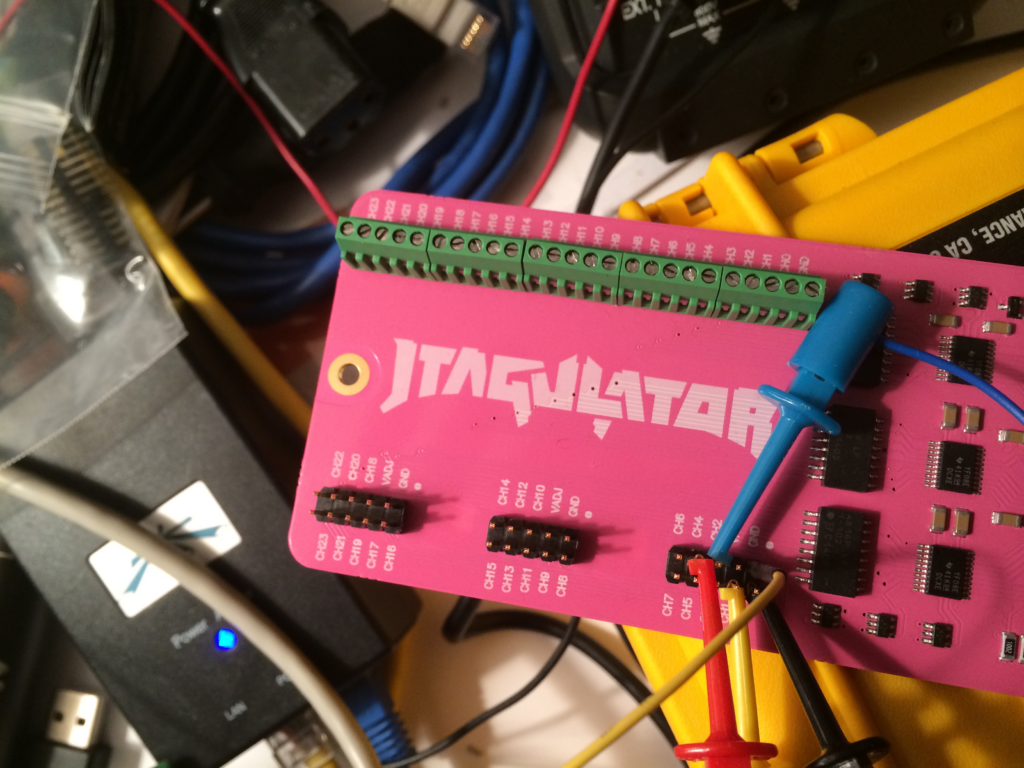
Connect to the Cambium 2400SM on the 2nd 5 pin wide row, counting from the ethernet port:
123456
0x0000
0x0000
0x0000
0x0000
0x0000
connect to the pins Ch0 – Ch 4 on Jtagulator.

Next, we will find the pinouts by asking the jtagulator what it can determine. If we can then read the device ID’s, we have successfully connected to the jtag interface. For the following boundary scan results, the Bold Italicized values were the confirmed values.
:i
Enter number of channels to use (3 – 24): 5
Ensure connections are on CH4..CH0.
Possible permutations: 60
Press spacebar to begin (any other key to abort)…
JTAGulating! Press any key to abort…
TDI: N/A
TDO: 1
TCK: 0
TMS: 2
IDCODE scan complete!
:
Number of devices detected: 9
TDI: 3
TDO: 1
TCK: 0
TMS: 2
Number of devices detected: 2
TDI: 2
TDO: 1
TCK: 0
TMS: 4
TDI: N/A
TDO: 1
TCK: 0
TMS: 3
TDI: N/A
TDO: 1
TCK: 2
TMS: 0
TDI: 4
TDO: 1
TCK: 3
TMS: 0 ?
Enter new TDO pin [1]: 1
Enter new TCK pin [3]: 3
Enter new TMS pin [4]: 0
Enter number of devices in JTAG chain [9]:
Device ID #2: 0000 0000000000000000 00011111111 1 (000001FF)
Device ID #4: 0000 0000000000000000 00000111111 1 (0000007F)
Device ID #6: 0000 0000000000000000 00000000111 1 (0000000F)
Device ID #8: 0000 0000000000000000 00000000001 1 (00000003)
Device ID #9: 0111 1111111111111111 11111111111 1 (7FFFFFFF)
__________________________
Number of devices detected: 61
TDI: 4
TDO: 1
TCK: 3
TMS: 0
____________________________
TDI: N/A
TDO: 1
TCK: 3
TMS: 4
😀
Enter new TDO pin [0]: 1
Enter new TCK pin [0]: 3
Enter new TMS pin [0]: 4
Enter number of devices in JTAG chain [9]:
Device ID #2: 0011 1111111111111111 11111111111 1 (3FFFFFFF)
Device ID #4: 0000 0111111111111111 11111111111 1 (07FFFFFF)
Device ID #6: 0000 0001111111111111 11111111111 1 (01FFFFFF)
Device ID #8: 0000 0000001111111111 11111111111 1 (003FFFFF)
IDCODE listing complete!
_____________________________
TDI: N/A
TDO: 1
TCK: 4
_______________________________
TDI: N/A
TDO: 1
TCK: 3
TMS: 4
TDI: N/A
TDO: 1
TCK: 4
TMS: 2
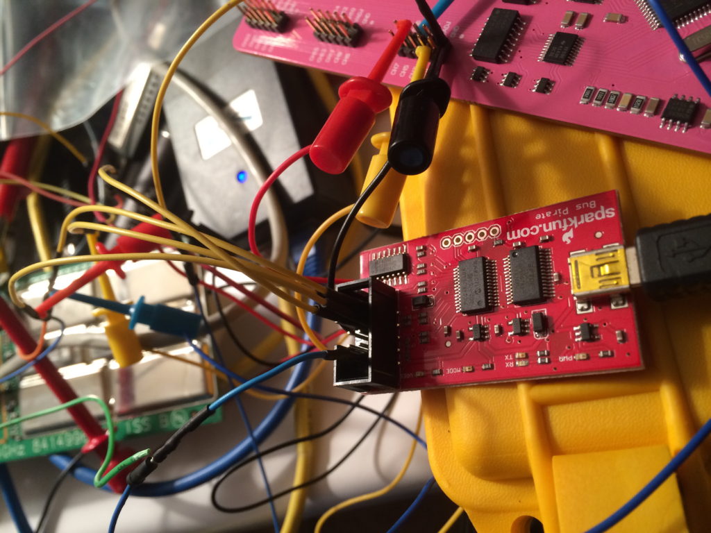
Pinouts for OpenOCD
http://dangerousprototypes.com/docs/Bus_Pirate_JTAG_connections_for_OpenOCD
BP-JTAG cable pinout
BP – JTAG
VPU – VTref(3v3)
GND – GND
MOSI – TDI
MISO – TDO
CLK – TCK
CS – TMS
N/A – TRST
N/A – RTCK
AUX – SRST
For this cable to work you need in your buspirate.cfg
buspirate_vreg 0 # turn off the voltage regulator
buspirate_mode open-drain # open drain as we are working with pull up’s
buspirate_pullup 1 # turn pull up’s on (VTref is connected to pull up’s)
- Note: # comments may not be allowed in the latest release
If you want to go with
buspirate_mode normal
buspirate_pullup 0
then don’t connect VPU and Vtref.